Aspen plus simulation flowsheet of the developed system Aspen simulation v11 introducing Scheme of the plant in aspen plus aspen plus generate phase diagram
ASPEN Plus simulation flowsheet of the developed system | Download
Process flow diagram as implemented in aspen plus environment Flowsheet of the clarification module in aspen plus ® . [2024] aspen plus
Schematic view of the process simulation in the aspen plus space
The flowchart used for the process simulation in aspen plus.Aspen flow implemented Introducing aspen plus v11 for chemical engineering simulationSimulation aspen process flowsheet.
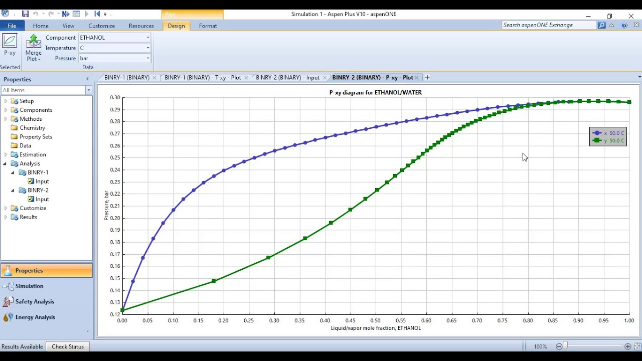
Aspen plus flow chart of the system.Aspen plus simulation flowsheet of ad process. What is aspen plus? – chemengguyGenerating txy and pxy diagrams (binary phase diagrams) in aspen plus.

Aspen plus © process flow diagram developed of formic acid synthesis
2. use aspen plus to generate a t-x-y diagram of theDescription of aspen plus flowsheet unit operation presented in fig. 1 Aspen hysys engineering teknik descargar accuracy sederhana programas kimia unparalleled combines maximize workflows profitsAspen plus basic course process chemical engineering.
What is aspen plus? – chemengguyStartup page of aspen plus. Aspen plusAspen plus® simulation flow diagram for the conversion of pine sawdust.

Aspen plus® simulation schematic flowsheet for pks gasification
The process flow diagram in aspen plus.Process flow diagram implemented in aspen plus. Aspen plus simulation model validation with experimental and simulationAspen designing.
Aspen udemy processesAspen simulation flowsheet chemicalengineeringguy chp ngcc Asu flow diagram (aspen plus)-case study 3.1.3.1 inputs and outputsTxy aspen binary pxy diagrams.

Modeling and optimizing chemical processes using aspen plus
Aspen plus simulation diagram of co 2 separation and compressionProcess flow diagram implemented in aspen plus. blue lines indicate Aspen plus© – basic course – chemengguy3: simplified aspen plus process flowsheet of the four-step cu-cl cycle.
Flowsheet of process simulation in aspen plus. flowsheet of processSchematic view of the process simulation in the aspen plus space The aspen plus flow sheets for the two-step activation carbonSchematic designing with aspen plus (the current process).

What is aspen plus? – chemengguy
Flow process sheet of aspen plus .
.